SWAMP COOLER WIRING
and WATER LINE HOOK-UP
An easy project for any handy Do-It-Yourselfer
 Welcome to our Do-It-Yourselfer swamp cooler wiring article. If you arrived here directly from the internet, you may want to visit our other swamp cooler information and swamp cooler installation pages first, and then return here.
Swamp Cooler Installation: Ductwork
Swamp Cooler main page: All about the "Swamp"
Swamp Cooler Maintenance
Swamp Cooler Roof Installation
The best time to rough in your swamp cooler wiring and water line for your new cooler is after the holes are cut through the roof and ceiling, but before the ductwork is installed.
The attic will be relatively cool because of the natural ventilation of the heat exiting the roof. If the swamp cooler wiring can be done now without interfering with the ductwork installation, you will be a much happier Do-It-Yourselfer.
A 110 degree attic with blown in insulation is not a pleasant place to be crawling around, pulling wires and water lines.
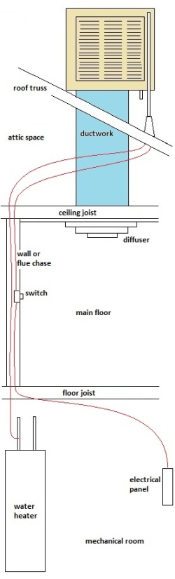
The diagram to the left is a very typical rambler style one level home with a basement mechanical room. Your home may be configured differently, but you should still be able to adapt the basic wiring and water line configuration into your home.
Routing
Often the best route for your swamp cooler wiring and water line between mechanical room and the attic is the flue chase. This is a very popular location for the wiring and water line, because the chase is accessible from both the basement or main level mech. room and the attic.
Once you have roughed-in the wiring and water line to the attic, simply pull across them across the attic space to your roof jack next to the cooler.
The water line
- Use 1/4" copper (preferable) or 1/4" plastic tubing. 1/4" pex may also be used, but takes special tools to prepare the joints.
- Make sure that the water line is not touching the flue. A plastic water line may melt and leak, and a copper one will rot away if touching a galvanized sheet metal flue.
- Do NOT install a coupling in the attic space. Couplings are prone to leaking and will likely destroy your ceiling without notice.
At the swamp cooler, the water hook-up is usually located on an exterior corner of the cooler. This is a direct connection to the float assembly inside the cooler.
Pull the water line out the top of the roof jack and route to this location. Ensure that there is upward slope to the float location. A low spot could hold water and freeze during the winter, causing a leak at start-up time in the spring.
The other end ties into the cold water supply line in the mechanical room. a shut-off is mandatory here, in case of a leak. Self-piercing saddle valves are available for this purpose. But, saddle valves are undependable. A better option is a tee soldered into your supply line, a shut-off valve, and a reducer for 1/4" tubing.
 The swamp cooler wiring
Determine first the best location for the switch. This can be tricky, as the route must communicate with unfinished space to the power source, and also communicate with the attic. Once again, if it is practical, placing the switch on the outide of the flue chase can be a good option.
- Make sure that the wiring does not touch the flue. The heat from a flue can melt the outer coatings of the wire, and is a fire hazard.
- Use 12/2 w/ground for the supply end, from the power source to the switch.
- Use 12/4 w/ground for the control end, from the switch to the swamp cooler. On the cooler end, during rough-in, leave plenty of extra length. The power junction box is up high inside the cooler cabinet. Use 1/2" rigid conduit with weathertite fittings for attachment to the cooler.
Residential 110 volt wiring is fairly uncomplicated and easy to understand, however some folks are not comfortable working on any wiring. If this is you, contact a professional electrician to complete this part of the installation.
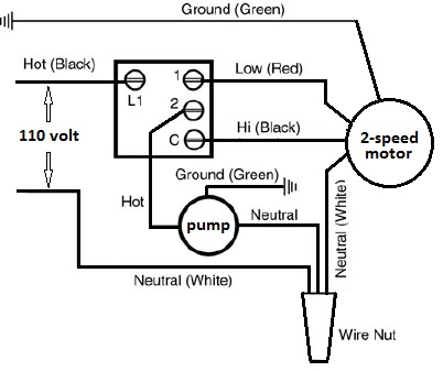
Refer to above diagram
The green ground wires never carry electricity. They are a safety "path to ground" to reduce the chances of shock and injury. The white wire is the common. This wire is dead and carries no electricity until the switch is turned to one of the operational postions. Then the line is live and completes the circuit back to the power source.
Utilizing this type of switch for your 2-speed cooler, the settings are:
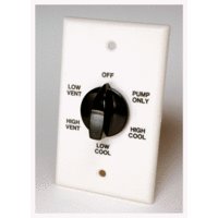
Off
Vent or Fan (LO)
Vent or Fan (HI)
Cool or Fan (LO with pump)
Cool or Fan (HI with pump)
Pump only
Vent only (hi or lo) is used for circulation of outside air through the home when cooling is not needed.
The pump only setting is used before each use of the cooler. Turn the pump on for 10 minutes to thoroughly wet the pads before use.
The cool settings (hi or lo) is full operation with pump wetting the pads and blower distributing cooled air into the residence.
The switch pictured here is the most common switch available for a conventional downdraft or sidedraft swamp cooler installation. This is a two speed switch with fan only option and pump only option.
The swamp cooler wiring pictured and explained here is unnecessary if you are installing a window mount cooler or a sidedraft style window cooler. Both of these simply plug into the wall, and utilize the provided switch on the front of the discharge grille.
Return to Swamp Cooler main page
Return to Swamp Cooler Ductwork Installation
Return to Do-It-Yourself Hvac System page
Depart "Swamp Cooler Wiring" and Return to HOME
Enjoy this page? Please pay it forward. Here's how...
Would you prefer to share this page with others by linking to it?
- Click on the HTML link code below.
- Copy and paste it, adding a note of your own, into your blog, a Web page, forums, a blog comment,
your Facebook account, or anywhere that someone would find this page valuable.